Continuing from the post on January 5th………
With the molds completed, it was time to fire up the furnace!!!!!!!!!!!!!
To melt the scrap gears, a crucible-style furnace was used.
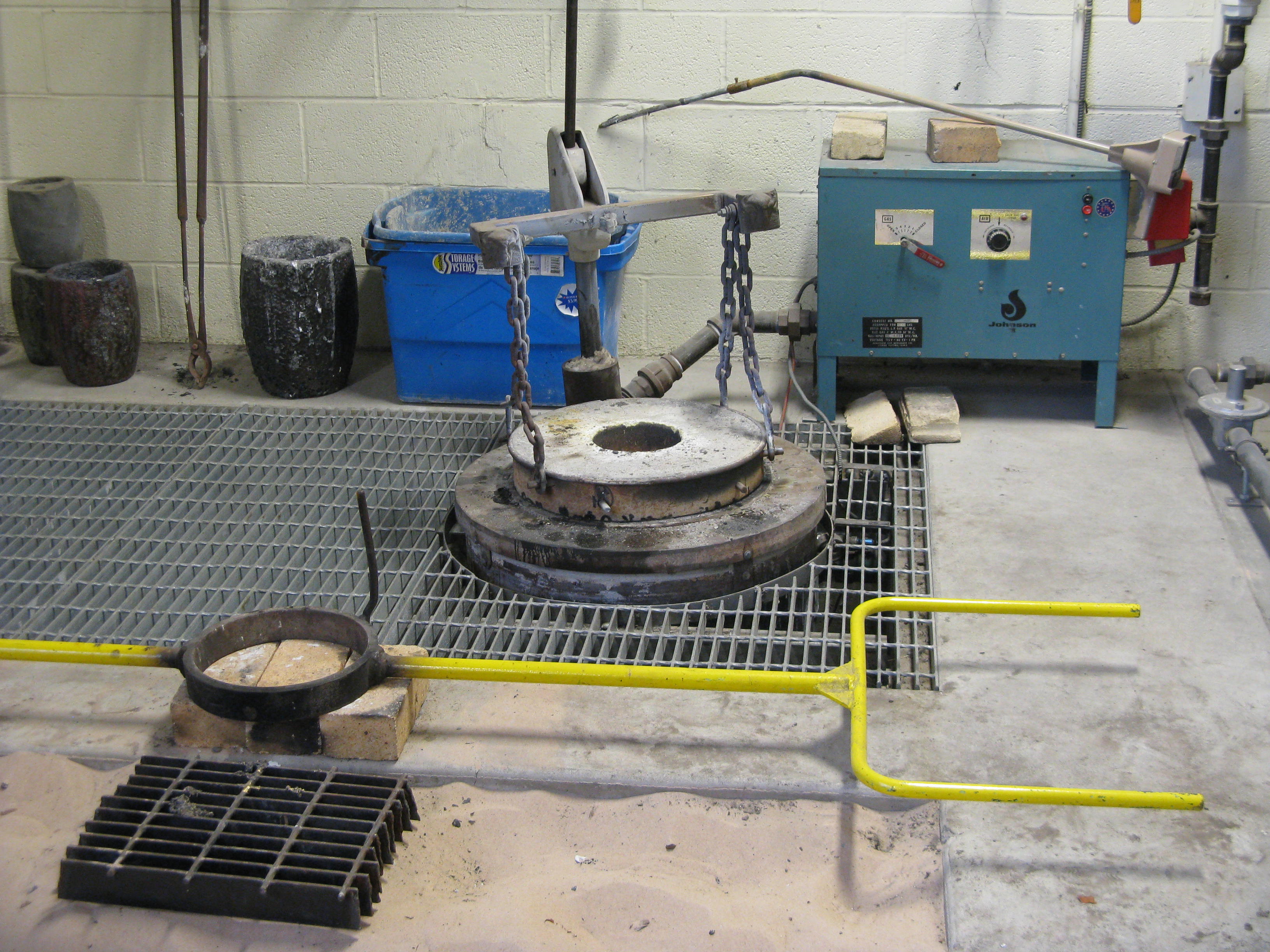
The furnace is lined with a refractory material that can withstand high temperatures and placed in the center of it is a ceramic crucible (there are few sitting against the back wall in the image). To operate the furnace, a gas-air mixture is ignited which passes around the crucible. The crucible subsequently heats up and melts metal placed within it.
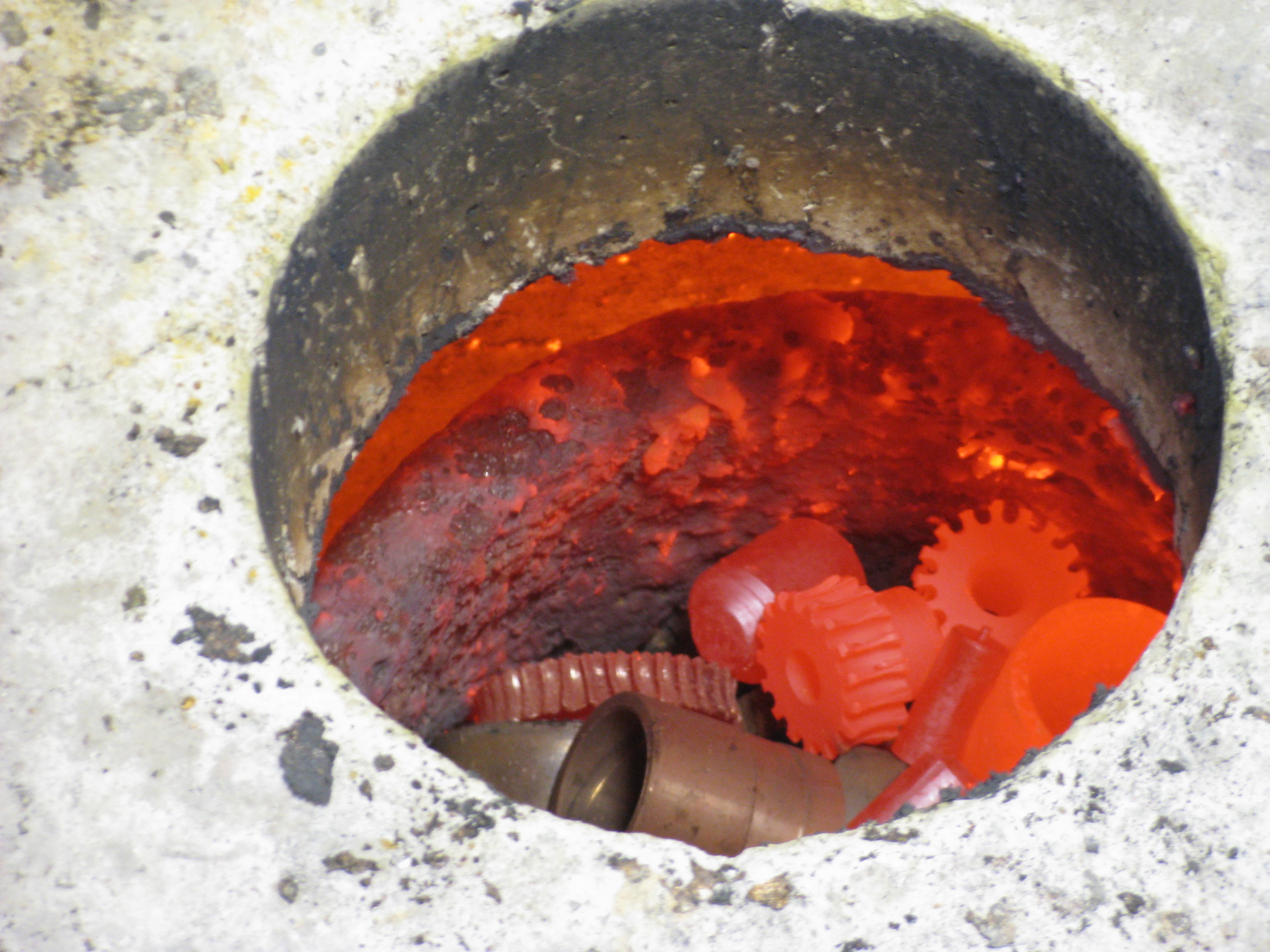
In the image above, the gears are heating up red hot and will soon liquefy.
With the bronze liquid and at a temperature of 2300 degrees Fahrenheit (measured with a pyrometer), the lid of the furnace was slid off, the crucible was lifted out it using a large set of tongs, and then placed into a holder called a shank.
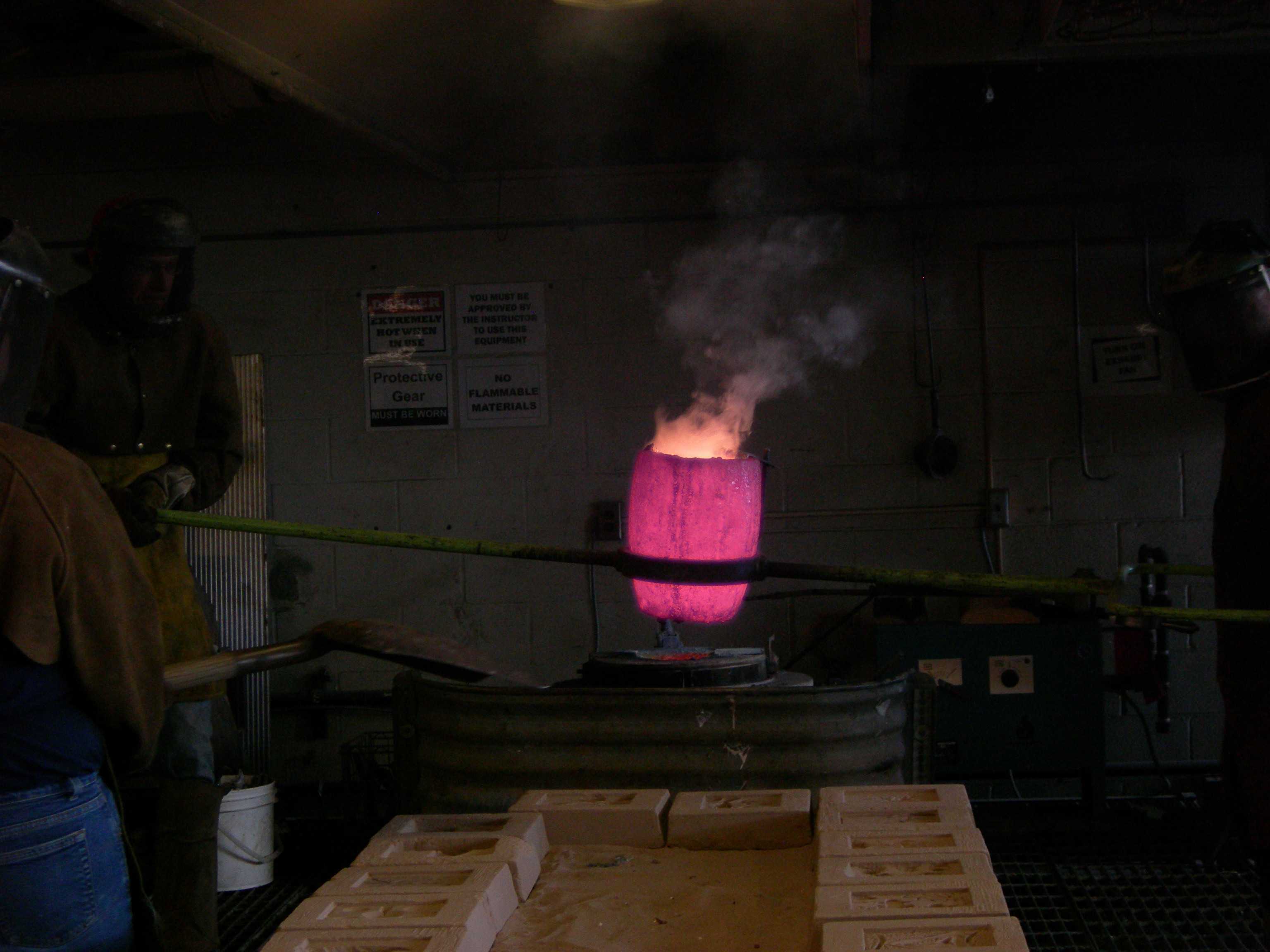
The above and below images are from a difference pour, but show what the crucible looks like when outside of the furnace.
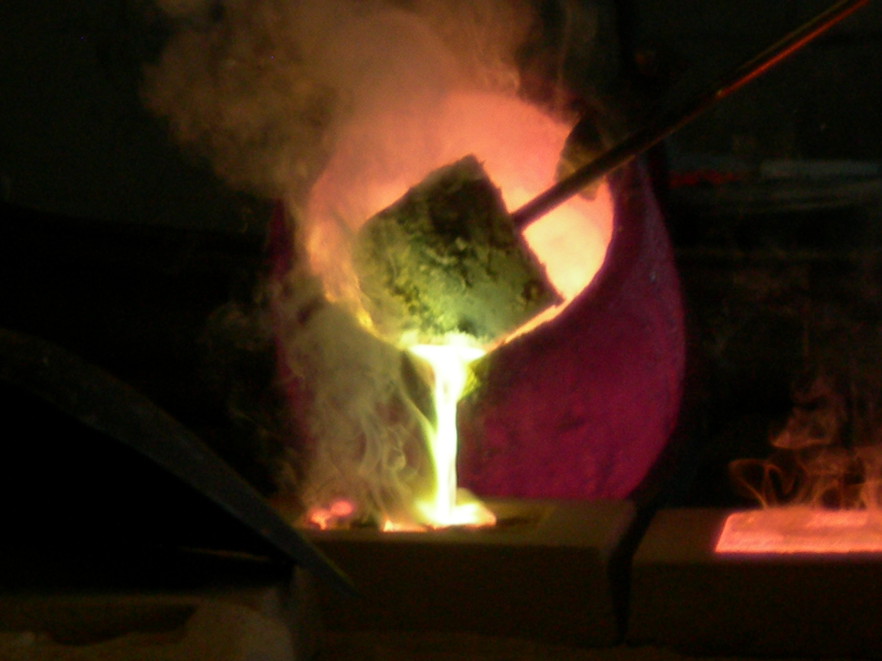
The molds were carefully filled and then covered with sand to hinder the loss of heat from the exposed metal to help get a uniform rate of cooling throughout the castings.
After the molds had cooled, they were broken apart exposing the castings within.
In the image above, the spindle valves can be seen while the lower images shows the back of the steam exhaust flange.
With the parts cast, some time remained to being work on cutting threads into the parts.

In the image above, John takes a measurement of the thread count from a wax copy of the steam exhaust flange.
The newly cast flange was then cut free of its pour system, planed, and mounted into a lathe for machining.
The first step in cutting the threads was to adjust the mounting end to the correct diameter by removing some material.
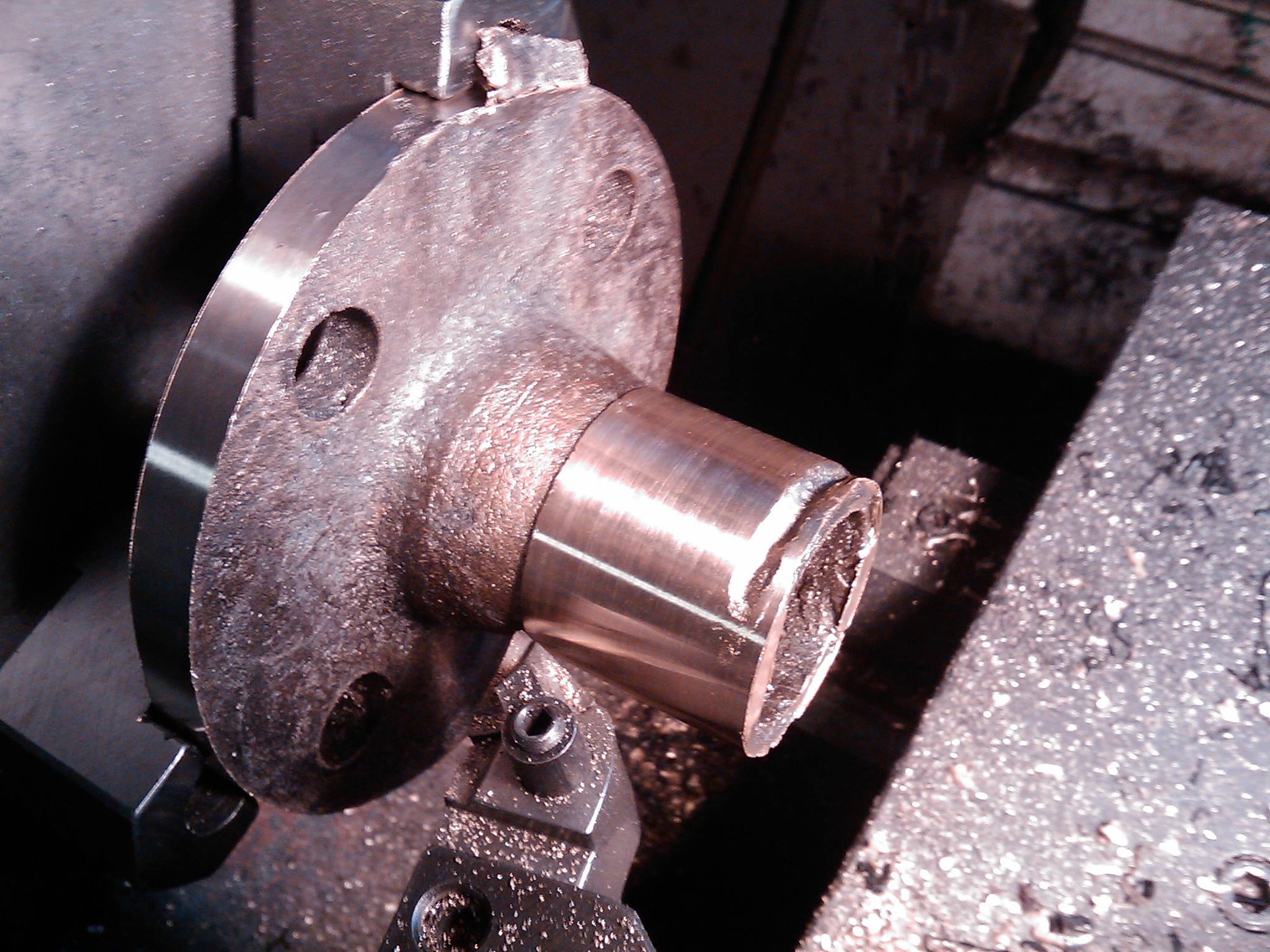
The threads were then cut into the flange.

Well that’s it for now from Worthington casting central!!!!!